
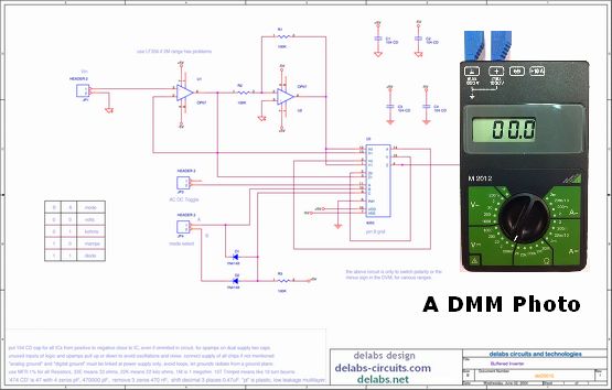
Here the 4053 selects or routes the voltage, current or resistance measurements to the A-D converter or display. It is selected with the mode selection when you want to measure Volts, Amps, Ohms and AC-DC. Some have to be polarity inverted and some signals just buffered this is selected and done by this circuit according to the digital control.
Analog Buffer and Inverter Switching
Now U1 OP07 circuit is a Buffer unity gain and low offset, U2 circuit is unity gain but polarity of output is opposite of input. D1-D2-R3 form a AND gate to select diode-buzzer test mode. The digital selection of 4053 Analog-Switch does not produce any errors in the analog-switching of even mV signals. But it works best at +/- 7.5V dual supply pin-16 is +7.5V, pin- 8 is digital ground and pin 7 alone should go to -7.5.

Analog ground can be same as digital ground, or the switched signals must be within +/-5V of digital ground. The switches should not carry any current and should be buffered at the output by FET opamps 1-Tera-Ohm. Then alone measurements are ok, as the switches have ohmic resistance.